
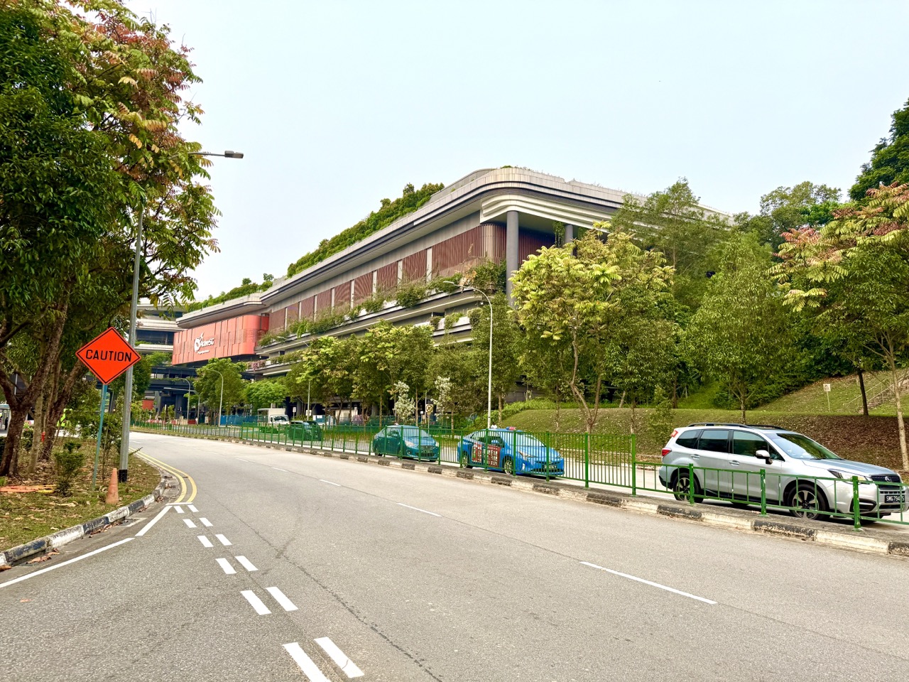
ActiveSG Punggol Sport Centre at 11 Sentul Crescent is a useful local reference for understanding Geotechnical Engineering: the engineering of soil, rock, groundwater and the interaction between the ground and structures. A building needs foundations suited to the conditions below it, while an excavation may require carefully designed support and monitoring. However, an exterior photograph cannot tell us which soil layers exist beneath the Sport Centre, whether its foundations are shallow or deep, or what its groundwater level is. The centre began selected public operations on 27 October 2026, with formal opening scheduled for 22 November 2026. Students should learn from verified professional sources and fictional cross-sections, not dig in public landscaping, enter construction worksites or attempt to inspect foundations. Real facility access remains on MyActiveSG+.
Singapore’s Building and Construction Authority’s structural-plan guidelines explain the role of site investigation, geotechnical data, engineering parameters, earth-retaining structures and qualified professionals. BCA also identifies accredited site-investigation firms and its standardised AGS(SG) geotechnical data format. An IIT Kharagpur soil-mechanics course distinguishes soil properties and strength from foundation design, and IIT Madras’ foundation-engineering curriculum covers effective stress, permeability, consolidation, bearing capacity and retaining structures. These are authoritative disciplinary ideas, not technical test results for Punggol. The lesson is to understand how engineers investigate uncertain ground, distinguish observations from assumptions, design for appropriate load and water conditions, and monitor risk under qualified supervision.
- Local reference: Punggol Sport Centre, 11 Sentul Crescent; actual geology and foundations are not established here.
- Ground investigation: study site history, available geological information, boreholes and suitable field or lab data through qualified processes.
- Soil and rock: different materials have different properties, structure and weathering states.
- Grain sizes: gravel, sand, silt and clay are classification concepts, not assumptions about one real site.
- Porosity and void ratio: quantify volume relationships among soil solids and voids.
- Groundwater: influences pore pressure, effective stress, seepage and construction conditions.
- Effective stress: a central soil-mechanics concept involving total stress and pore-water pressure.
- Strength and settlement: bearing resistance and deformation are separate performance questions.
- Foundations: shallow and deep options depend on load, site constraints, design and verified ground evidence.
- Excavations: retaining systems and instrumentation require professional design and control.
- Safety: never dig or probe near public utilities, slopes, canals, excavation fencing or building foundations.
- Learning route: terminology, original numerical examples, interpretation, uncertainty, four-week study programme and FAQs.
Definition lock: Geotechnical Engineering studies the ground
Geotechnical Engineering investigates and designs around the mechanical behaviour of soil, rock and groundwater. It asks whether ground can provide adequate support, how it deforms under load and how excavation or changes in water conditions may affect surrounding structures. The relevant properties are not visible from the colour of a building’s exterior. A student’s first principle should be uncertainty: the ground varies with depth and location, so design must be informed by suitable investigations. A modern building does not by itself reveal its foundation type, soil composition or performance margin. Technical conclusions require qualified evidence.
Why this is not another Structural Engineering article
Structural Engineering studies the response of beams, columns, slabs, frames and whole structures to loads. Geotechnical Engineering examines the ground supplying support and the interaction of foundations or retaining structures with it. A roof load eventually reaches a foundation, but the ability of the ground to resist loading and limit settlement is a separate question. Both disciplines coordinate. A student who understands a column’s compression formula has not thereby established a soil’s bearing resistance. This guide focuses on site investigation, soil behaviour, pore pressure and geotechnical design principles, not another roof-load or architecture description.
Why this is not the drainage guide
Environmental Engineering may trace rainwater across roofs, landscaped areas and managed stormwater paths. Geotechnical Engineering examines how groundwater and pore-water pressure affect the soil mass itself, foundation stability and excavation behaviour. Water connects the subjects but their core goals differ. A rain garden’s runoff treatment performance does not establish a building’s subsurface foundation parameters. A student can draw a conceptual surface-water path and a separate groundwater level, then explain why the two cannot be equated without site evidence. No actual Punggol Waterway samples or public drain inspections are needed for the comparison.

Begin with a desk study
Before field investigation, professionals examine available site history, geological information, nearby developments and relevant existing records. BCA’s site investigation guidance identifies geological maps and historical borehole information as useful resources for appropriately qualified design teams. This does not mean a student should obtain private site reports or declare an exact underground cross-section from an old map. A desk study informs the scope of further investigation; it does not replace site-specific data. The educational exercise can use a completely fictional map with labelled uncertainties. A good report clearly states which facts are documented and which need verification.
Why soil is not a uniform solid
Soil is a mixture of mineral or organic particles, void spaces and possibly water and air. The particle sizes, arrangement, density and stress history can differ among layers and locations. A shallow sample does not necessarily represent ground many metres below. Students should avoid saying “Punggol soil is soft” or “every site here is reclaimed sand” without real geological or investigation evidence. Different ground conditions can occur across a district. Geotechnical models use sampled and inferred properties with appropriate uncertainty. A clear fictional layered diagram can teach the concept without making unsupported claims about the Sport Centre itself.
Rocks and soils require different descriptions
Rock masses may contain joints, fractures, weathered zones and variations in material strength, while soils behave through particle contacts, pore fluids and other mechanisms. Some weathered rock can behave differently from intact laboratory specimens. A learner should not assume a visible stone proves that the entire foundation sits on hard bedrock. Engineers describe material and discontinuities using appropriate classification and investigations. The difference matters because load transfer and excavation methods depend on the actual ground. A school diagram can show an imagined soil layer over jointed rock, clearly labelled as a possible abstract profile rather than actual site conditions.
Grain size is one classification factor
Soils are often discussed using coarse fractions such as gravel and sand and finer fractions such as silt and clay, with definitions set by the relevant standard. However, particle size alone does not establish all mechanical behaviour. Mineralogy, moisture, density, plasticity and structure also matter. A student may compare illustrations of differently sized particles and ask how their arrangements influence water paths. Do not collect soil from public planters or expose unknown samples in an unsupervised class experiment. The educational goal is to recognise categories and questions, not assign a formal soil classification to one Punggol location.
Sand and clay can behave differently
Many sands transmit water relatively readily under suitable conditions, while some clays have low hydraulic conductivity and may show significant time-dependent deformation. These are broad tendencies, not absolute rules. A particular dense sand, mixed soil or fissured clay can behave differently from the simplest school cartoon. Geotechnical design requires actual classification and test results. Students should avoid using the words sand and clay as though they specify one universal strength or settlement value. The right principle is that material properties depend on composition and structure, and that water and loading can change the relevant behaviour.
Particle shape influences packing
Rounded and angular grains may pack and interact differently under comparable conditions. The grading distribution, particle shape and compaction history influence the arrangement of voids and contacts. A student can draw imaginary circles and angular polygons packed inside a box, then compare the possible spaces between them. Such drawings cannot calculate a real engineering strength without appropriate assumptions and tests. The exercise is useful for seeing why grain size alone may not determine behaviour. It should not be promoted as a certification of sand sourced from a real building site or a public landscaping area.
Voids include water and air
Soil voids are the spaces between its solid particles. They may be filled with air, water or both depending on conditions. A fully saturated conceptual soil has its voids filled with water, but that does not mean the solid particles disappear or that the material becomes a free-flowing liquid. Students should draw the three-phase model with solids, water and air before using equations. This is a simplified representation, and actual natural soils can have complex behaviour. The diagram teaches quantities and definitions without removing samples from a public place or conducting physical soil tests.
Porosity is a fraction of total volume
Porosity n is Vv/V, the void volume divided by total volume in a defined soil sample. If a fictional sample has total volume 100cm³ and void volume 35cm³, porosity is 0.35 or 35%. The number says how much volume is void space under the model; it does not directly measure hydraulic conductivity or bearing resistance. A student should be careful not to confuse volume of voids with volume of water when the soil is only partly saturated. This arithmetic can be done on paper. The invented values are not measurements from Punggol ground.
Void ratio uses the volume of solids
Void ratio e is Vv/Vs, comparing void volume with solid volume rather than total volume. For the fictional sample with 35cm³ of voids and 65cm³ of solids, e=35/65≈0.5385. Porosity is 0.35 for the same example. These numbers differ because the denominators differ. Their relationship is n=e/(1+e) when the volumes are defined consistently. Students should derive this from V=Vs+Vv rather than memorise it without meaning. The formula concerns volumetric structure, not a direct safety rating for a foundation.
Saturation is not the same as porosity
Degree of saturation S is commonly defined as Vw/Vv, the fraction of void volume filled with water. If an invented soil sample contains 35cm³ of voids and 21cm³ of water, its saturation is 21/35=0.60, or 60%. Porosity remains 35% of the total sample volume in the preceding setup. Students may confuse the two percentages because both involve water-related spaces. The first describes how much of the sample is voids; the second describes how much of those voids contain water. The definitions should appear beside every equation.
Bulk density and dry density differ
Bulk density considers the mass of soil in its current moisture condition per unit total volume. Dry density uses mass of dry soil solids divided by total specimen volume under the relevant definition. A student must not assume the two values are equal when water is present. Density also differs from unit weight, which is force per volume and includes gravitational acceleration. A class can compare fictional mass and volume values, but actual geotechnical density testing requires suitable methods and sample quality. The scientific value comes from understanding which mass and volume were measured, not inventing a site-specific engineering number.
Compaction reduces some void space
Compaction applies mechanical energy to densify suitable soil under controlled conditions, often reducing air voids while moisture content influences the outcome. It is different from long-term consolidation caused by drainage and sustained loading. Students should not attempt to compact public landscaping or assume trampling a path improves engineering stability. Professional compaction requires specified material, equipment, moisture control and verification. A paper diagram comparing loosely arranged and more densely arranged particles can introduce the concept. The physical performance of the actual ground depends on tested properties and appropriate field quality control.
Consolidation occurs through time-dependent drainage
In soil mechanics, consolidation commonly refers to volume change associated with expulsion of pore water under sustained changes in stress, particularly relevant to saturated low-permeability soils. The process may take time because water needs to move through the pore network. This differs from instant elastic deformation and from mechanical compaction. A student can draw a fictional saturated soil layer under a load and arrows indicating gradual drainage. No physical pressing of wet soil or testing of public ground is required. The lesson is why settlement may develop over time and why groundwater conditions matter.
Groundwater is not necessarily at a constant depth
The groundwater table and pore pressure distribution may vary with rainfall, drainage, construction and other conditions. A conceptual cross-section can show a chosen water level, but that line is only a model unless verified by suitable investigation and monitoring. Students should not use a nearby Waterway surface elevation to infer exact pore pressure beneath the Sport Centre. Actual groundwater observations need appropriate instruments and qualified interpretation. The distinction protects against false engineering claims. One visible body of water does not define the subsurface flow field around every nearby foundation.
Pore-water pressure affects soil stress
Pore-water pressure is the pressure within water occupying soil voids. For a simple static hydrostatic condition, u=γw h relates pore pressure at depth h below a reference water level to the unit weight of water. Real groundwater flow can create nonhydrostatic distributions, so this equation has assumptions. A student can calculate invented values using suitable units without observing actual soil. The key concept is that pore water contributes to how loads are distributed in a saturated soil skeleton. A calculation of u is not automatically a foundation stability check.
Effective stress is a central principle
For a saturated soil under appropriate conditions, the effective-stress concept is often written σ’=σ−u, where σ is total stress and u is pore pressure. It explains why the soil skeleton’s mechanical behaviour depends on stress carried by particle contacts rather than total stress alone. A student should define the stress direction and model assumptions. This is not a universal equation for every complicated multiphase or dynamic condition without qualification. IIT’s soil mechanics courses treat effective stress as foundational. A paper example can illustrate the relationship without measuring actual Punggol groundwater.
Worked effective-stress calculation
Suppose an imagined soil point has total vertical stress 100kPa and pore-water pressure 40kPa under a simple one-dimensional model. Effective vertical stress is 100−40=60kPa. If total stress were unchanged but pore pressure increased to 50kPa, effective stress would decrease to 50kPa. This calculation illustrates the relationship, not an actual situation under the Sport Centre. Students should not infer settlement or failure directly from the two numbers, because strength, stress history and additional conditions matter. The output is one stress quantity in a model, not a complete geotechnical design.
Permeability controls how water can pass
Hydraulic conductivity describes how readily water moves through a porous medium under a hydraulic gradient and given conditions. Grain arrangement, pore sizes and fluid properties matter. A soil with large connected pores may allow water to pass more readily than a fine-grained low-permeability material, but broad visual categories are not enough for design. Students should not pour dyes, detergents or other materials into public soil or drains to test flow. A conceptual diagram can show connected pores and a pressure gradient. The real parameter requires suitable tests and consideration of site variability.
Darcy’s law is a simplified flow relationship
Under appropriate flow conditions, Darcy’s law expresses discharge through a porous medium as Q=kAi, where k is hydraulic conductivity, A cross-sectional area and i hydraulic gradient, with sign conventions handled appropriately. It is an empirical relationship applied under certain conditions and does not describe every turbulent or complex subsurface flow without refinement. Students can solve a fictional problem with supplied k, A and gradient, but must not treat the result as the actual flow beneath Punggol Waterway. The material and geometry need definition, and real design requires verified parameters and appropriate methods.
Worked seepage-flow example
Take fictional hydraulic conductivity k=1×10⁻⁵m/s, flow area A=2m² and hydraulic-gradient magnitude i=0.5. Darcy’s simplified discharge magnitude is Q=kAi=1×10⁻⁵m³/s. This equals about 0.01 litres per second, under the assumptions. The number is educational, not a measurement from any Punggol soil or drainage system. Ask students why the unit is volume per time and how changing the flow area affects the model. Actual subsurface water flow is far more complex, and no engineering decision can be made from this isolated calculation.
Groundwater flow and surface runoff are distinct
Rainwater running across a roof or pavement is surface runoff, while groundwater moves through soil and rock pores and fractures under appropriate hydraulic conditions. The processes can influence each other through infiltration and drainage, but they should not be treated as the same flow path. The previous Environmental Engineering guide discusses urban stormwater conveyance; here the emphasis is water pressure and movement within the ground. A student can draw two arrows on a fictional cross-section and state the differences. There is no need to access a public drain or waterbody to understand the contrast.
Shear strength governs resistance to sliding
Soil shear strength describes resistance to deformation or failure along possible shear planes under given conditions. It depends on material properties, effective stress, drainage and other factors. A common simplified effective-stress framework uses parameters associated with cohesion and friction angle, but the proper values and interpretation require qualified testing. Students should not assume all clay is weak or every dense sand is safe. A simple diagram of a block on an inclined plane may provide intuition without replicating real soil behaviour fully. Actual slope and foundation stability analysis needs professional design.

Mohr–Coulomb is a model, not a universal soil law
An introductory shear-strength relationship is often written τ=c’+σ’ tanφ’ under relevant effective-stress conditions. It combines a modelled cohesion intercept with an effective normal-stress contribution through a friction angle. The parameters are not automatically constant in every soil or loading state. Students should identify which quantity is stress, which is an angle and what must be tested. A textbook calculation can explain the structure, but it cannot certify the strength of actual ground. Real projects use appropriate constitutive assumptions, investigation data and design standards, not a single unverified friction-angle guess.
Bearing pressure differs from bearing capacity
Applied bearing pressure concerns how a foundation load is distributed over its contact area under a chosen model. Bearing capacity concerns the ground’s ability to resist loading without an unacceptable failure mechanism. A student should not calculate load divided by area and call the result the allowable bearing capacity. The first is a demand measure, while the second requires analysis of soil resistance and other factors. Geotechnical design also checks settlement. A structure may meet one criterion yet have a problem with another. The concepts must remain separate for safe and accurate reasoning.
A simple pressure calculation
Suppose a fictional foundation carries a vertical load of 1,000kN over an idealised uniformly loaded area of 10m². The average applied bearing pressure is 100kPa. This is not a design for Punggol Sport Centre and does not establish whether the soil can support it. Students should calculate the units and then ask what additional evidence would be necessary: soil strength, groundwater, settlement, loading eccentricity and applicable standards. The number represents an assumed demand in a simplified model. Engineering safety is a separate professional judgement requiring credible site data and proper calculations.
Settlement is deformation, not necessarily collapse
Settlement refers to downward movement or deformation of a foundation or the supporting ground under loading or other relevant conditions. A structure may remain standing while experiencing movement that affects serviceability, levels or connections. Some settlement may be expected and accommodated by design, while excessive or differential settlement may be problematic. Students should not interpret one floor crack or photograph as evidence of foundation settlement at a named building. Proper assessment requires qualified investigation, monitoring and structural context. The geotechnical question concerns the magnitude, distribution and consequences of deformation, not simply whether a structure falls.
Total and differential settlement are different
Total settlement describes movement of a point or foundation relative to an appropriate reference, while differential settlement concerns differences in movement between locations. Two nearby supports settling by the same amount can create different structural effects from one moving substantially more than the other. Engineers consider the geometry, stiffness and tolerances of the supported structure. A student can draw two imaginary columns on a paper base and show equal versus unequal downward movement. This does not diagnose any actual Sport Centre condition. The useful lesson is that spatial variation matters, not merely the largest measured movement.
Consolidation settlement may develop over time
A saturated low-permeability layer under sustained loading may experience gradual pore-pressure dissipation and volume change. That is why consolidation can produce settlement over an extended period in suitable soils. The time scale depends on drainage path, compressibility and material properties. A student should not infer a real building’s future settlement from its age or location. The mathematical principle can be illustrated by a fictional layer with a time-dependent compression curve, without trying to load wet soil at home. Engineers evaluate settlement using relevant site investigations and design assumptions.
Immediate settlement has a different interpretation
Some deformation occurs relatively promptly as a foundation or soil mass responds to loading, while other changes may develop slowly. The distinction depends on material conditions and the analysis model. Students should not assume every visible movement is consolidation, nor that all ground deformation must take years. Geotechnical engineering investigates the mechanisms and their appropriate time scales. A paper graph showing an immediate jump followed by a slower curve can build intuition, with a clear label that it is schematic. No real Punggol monitoring data are represented.
Shallow foundations transfer loads near the surface
Shallow foundation systems include suitable footings and rafts or mats that transfer structural loads into ground at relatively shallow depths, under appropriate design conditions. The actual choice depends on verified strength, settlement, groundwater, neighbouring structures and construction constraints. A student can sketch a column sitting on a fictional footing spreading load over a wider area. That diagram shows a concept, not an engineering detail or approved design. The learner should not claim the new Sport Centre uses a shallow foundation just because its visible columns stand on the floor. The foundations may be concealed.
Deep foundations transfer loads farther down
Deep foundations such as piles may transfer loads through shaft resistance and end bearing, depending on their type, ground and design. A student can draw an imaginary pile passing through several labelled soil layers and explain that load may be distributed along and near it. The sketch does not establish the actual depth, construction method or capacity of Punggol Sport Centre foundations. Real pile design requires professional geotechnical investigation, structural coordination and testing. A deep foundation is not automatically better than every shallow one; the suitable solution follows site conditions and performance requirements.
Pile type depends on site constraints
Different pile systems may be formed or installed through varied construction methods. Noise, vibration, spoil management, groundwater, access and nearby structures can influence selection. A student should not assume every pile is a precast element driven by impact or that every bored pile is quiet under all conditions. The topic belongs to qualified construction engineering and site-specific method statements. An introductory report can compare the broad principles through diagrams and official guidance. No one should enter a construction site to identify pile machinery or collect samples for a class.
Raft foundations spread load over an area
A raft or mat foundation supports multiple loads through a broader foundation element under an appropriate design. It may be useful in some site and structural conditions, but the actual suitability depends on settlement, strength and cost among other factors. Students can draw a simple foundation plate beneath several imaginary columns. They should not compute real structural reinforcement or apply a school formula to a six-storey building without credible technical data. The geometric concept is different from proving adequate capacity. Foundation choice is a professional design decision, not something inferred from a construction photograph.
Soil–structure interaction works in both directions
A structure applies loads to the ground, while ground deformation changes the forces and movements experienced by the structure. This mutual response is called soil–structure interaction. An overly rigid model of the building alone may miss important foundation behaviour, while a soil-only model may overlook structural stiffness. Students can connect a fictional support and compressible spring in a paper diagram to understand the feedback. That is not a complete numerical design method. The actual interaction requires qualified engineering and appropriate data. The topic shows why geotechnical and structural professionals must coordinate rather than work as unrelated disciplines.
Excavations change ground conditions
Removing soil creates space but also alters stresses and may affect groundwater and nearby ground movement. Excavations can require support systems, safe methods and monitoring. A student should never investigate a construction excavation by entering fencing, approaching an exposed edge or touching temporary supports. BCA’s structural-plan guidelines include Earth Retaining and Stabilising Structures, or ERSS, and requirements related to geotechnical works. The educational question is why removing material changes the mechanical situation. A diagram can show an idealised supported excavation without providing construction dimensions or procedures that could be misused in a real worksite.
Earth-retaining systems resist lateral effects
A retaining structure may be designed to resist pressure from soil and groundwater while limiting movement under relevant conditions. The design can involve walls, struts, anchors or other elements, depending on the project. Students should not assume a visible fence is a structural retaining system or that one generic wall drawing is appropriate for every ground. Professional ERSS design must account for loads, groundwater, stability, construction stages and effects on neighbouring structures. A safe paper sketch can label the possible forces. Actual selection and installation require authorised qualified engineers and construction professionals.
Excavation stages matter
A large excavation may proceed through carefully controlled stages, with support and monitoring at appropriate points. The temporary condition during construction can differ from the completed permanent structure. A student should not assume the final design drawing explains every intermediate construction risk. Temporary works require their own analysis, qualified coordination and adherence to approved methods. This is a central engineering insight: a structure may be safe in its final state but need suitable support as it is built. No unsupervised construction-site observation is necessary to learn the principle.
Slopes need stability assessment
Natural or engineered slopes may be affected by soil properties, water, geometry and external loads. The likelihood of movement cannot be determined solely from whether a slope looks green or dry in a photograph. A student can draw a fictional sloping soil mass and discuss driving versus resisting effects conceptually. Do not perform soil tests near a waterway bank or climb an unstable slope. BCA’s geotechnical guidance includes slope and stabilisation considerations for relevant building works. Actual assessment needs site information, appropriate investigation and qualified design. A classroom picture is a starting question, not a safety certificate.
Drainage and pore pressure affect slopes
Water conditions can influence effective stress and the stability of a soil mass. Changes in pore-water pressure may affect resistance under a chosen model, while surface runoff can create other erosion concerns. However, the exact cause of a slope problem depends on ground conditions and cannot be inferred from rainfall alone. A student should distinguish surface drainage from subsurface pore pressure. A paper diagram can show both arrows and explain how they differ. There is no need to approach a wet slope during a storm. Real hazards require immediate safe avoidance and appropriate professional reporting.
Site investigation gathers ground evidence
Professional site investigation may use boreholes, in-situ tests, samples, geophysical methods and monitoring as appropriate. BCA’s guidelines require site investigations for relevant building work to be undertaken and reported within its regulatory framework. The purpose is to obtain information to support engineering assessment, not simply to collect as much soil as possible. Students should not drill or dig on public property or near services. A classroom can interpret a fully invented borehole log to understand how ground layers are recorded. A real subsurface profile requires a legitimate accredited investigation and competent interpretation.
Borehole logs are records, not complete certainty
A borehole log describes observations and tests along a particular investigation location and depth, under the method used. Ground may vary between boreholes, and the geotechnical design team must evaluate that spatial uncertainty. Students should avoid drawing a perfect continuous flat soil layer across an entire site merely because two fictional logs show similar material at similar depths. The relationship between observations and inferred ground model needs reasoning. BCA’s standardised reporting aims to improve the quality and usefulness of records. An educational log should clearly say it is invented rather than representing Punggol’s actual underground conditions.
SPT and CPT are different in-situ test methods
The Standard Penetration Test and Cone Penetration Test are widely known field investigation methods for characterising ground under suitable procedures and interpretation frameworks. They measure different responses and are not interchangeable values. Engineers consider local geology, soil type, equipment, corrections and other factors when using results. A student should not take a single invented SPT number and announce a safe building load. Use a simple comparison chart listing the type of observation and the need for qualified interpretation. Actual tests are carried out by authorised accredited professionals, not home learners.
Laboratory tests require representative samples
Geotechnical laboratories may examine properties such as grain-size distribution, moisture content, density, shear strength and compressibility using appropriate standards. Sample disturbance can affect results, so quality of collection and handling matters. Students should not assume a handful of soil from a public planter represents a foundation bearing stratum. The correct class activity is to learn which property each test seeks and why it matters. Site-specific engineering requires suitable representative evidence across relevant layers and conditions. The discipline is about data integrity as much as arithmetic.
Geological maps cannot replace local investigation
A national geological map helps professionals understand regional formations and plan further study, but it cannot reveal every site-specific layer, groundwater condition or local variation. BCA’s guidance points to Singapore geological information as one input into investigation planning, not a substitute for all field tests. A student should label any hypothetical ground cross-section as a model and recognise that actual strata may vary. The Punggol Sport Centre’s foundation type and soil profile should not be invented from district-level generalisations. The proper conclusion is that more appropriate evidence would be required for a real engineering claim.
AGS(SG) is a data-format standard
BCA’s Singapore Geological Office introduced AGS(SG), a standardised electronic format for geotechnical investigation data, to support consistent reporting and sharing. This is a data-management tool, not a test method or claim that all ground conditions are identical. A student can learn that meaningful comparison requires consistent fields, units and metadata. A perfectly formatted file still needs accurate observations and competent interpretation. The classroom need not use private project databases; an invented table of depth, material and observations demonstrates the principle. Data quality and interoperability support engineering, but formatting alone cannot certify foundation safety.
Qualified Persons and accreditation are real boundaries
BCA’s current structural-plan guidance identifies responsibilities for appointed Qualified Persons and other relevant accredited participants. Site investigation firms and professional engineering reports operate under defined requirements for applicable works. A schoolchild who understands effective stress has not become an authorised geotechnical engineer. Nor should an independent website present its paper foundation sketch as an approved design. The correct educational lesson includes recognising authority and professional responsibility. Any actual building safety concern should go through appropriate official channels rather than informal digging, repair or diagnosis by visitors.
Instrumentation can monitor change over time
Geotechnical monitoring may include measurements related to ground movement, water pressure or forces, depending on the project and engineering purpose. The specific instruments, thresholds and action procedures require professional design. A student can draw a fictional time-series chart of settlement readings and discuss why reference points, instrument accuracy and measurement dates matter. They must not attach sensors to public structures, open protective cabinets or attempt to obtain confidential records. Monitoring can help manage risk, but it does not replace sound initial investigation and design. A numeric trend needs trustworthy provenance and interpretation.
A hypothetical settlement-monitoring chart
Imagine an invented monitoring point with vertical movement readings of 0mm at baseline, 1mm later and 2mm at a third observation. The student can describe the change, calculate an average difference and ask what would be needed before claiming a trend or danger. The values alone do not reveal measurement uncertainty, allowable limits or actual structural significance. A professional comparison requires instrument data, reference stability and engineering criteria. Never label this as Punggol settlement history. The example illustrates how measurement evidence supports investigation without pretending the classroom owns a building’s monitoring records.
Neighbouring structures must be considered

Excavation and foundation works can affect adjacent ground or structures through changes in stress, movement, vibration or groundwater, depending on the construction method and conditions. BCA’s regulatory framework includes impact assessment and relevant monitoring considerations. A student should not accuse a current building project of damaging neighbours without evidence. A paper case can show two fictional foundations at different distances from an excavation and ask which additional information is needed. The answer includes soil conditions, construction stages, structural details and qualified assessment. Public-safety statements require more than visual proximity.
Construction vibration is not always a foundation failure
Some construction methods produce vibration that nearby occupants may feel. Its presence does not by itself establish unsafe settlement or structural damage. The significance depends on frequency, magnitude, duration, distance, structure response and relevant standards. A student should not publish a diagnosis from a short phone video of a vibrating surface. At the same time, genuine safety concerns should be reported to responsible authorities or professionals. The educational goal is distinguishing observation, measurement and verified engineering consequence. A familiar physical sensation is not the same as a qualified geotechnical conclusion.
A paper foundation-selection case
Give students a fictional site with two soil layers, a groundwater line and a proposed light structure. Ask what further investigations and design checks would be required before selecting a shallow footing or pile foundation. Do not provide enough information to pretend a complete design is possible. The good answer identifies bearing resistance, settlement, groundwater, construction effects and applicable standards. This illustrates how engineers make decisions under uncertainty. A student who chooses a foundation type without data should learn to revise the claim to a conditional recommendation. There is no real Punggol foundation assignment involved.
A fictional porosity and void-ratio case
Suppose an imaginary soil specimen has 60cm³ of solids and 40cm³ of voids. Its porosity is 40/100=0.40 and its void ratio is 40/60≈0.667. If twenty-five cubic centimetres of the void space contain water, saturation is 25/40=0.625, or 62.5%. Students should explain the different denominators rather than guess from the percentages. The values are teaching data, not laboratory results. This original exercise connects arithmetic and Soil Mechanics safely without collecting or handling unknown real soil.
A fictional pore-pressure case
At an imaginary point, suppose total vertical stress is 120kPa and pore-water pressure 50kPa. Under a simplified effective-stress model, effective vertical stress is 70kPa. Ask what happens if the assumed pore pressure rises to 60kPa with total stress unchanged: the effective stress becomes 60kPa. A student should state the mathematical relationship while acknowledging that actual strength or settlement response requires further properties and modelling. No real groundwater elevation is established by the exercise. A correct stress calculation is not sufficient to certify a foundation or slope.
A fictional foundation-pressure case
An imagined footing carries an assumed centred vertical load of 600kN across 6m², giving average applied pressure 100kPa in a simple uniform model. Students should identify why this is not a safe bearing-capacity calculation. They need ground strength, settlement assessment, geometry, load eccentricity and other qualified information. If the fictional load doubles but the area remains fixed, average applied pressure doubles under the arithmetic model. The calculation illustrates demand rather than capacity. No one should apply this formula to the actual six-storey Punggol Sport Centre without professional design data.
A fictional borehole-log interpretation case
A classroom sheet contains two entirely invented borehole logs showing different layers at similar depths. Students should avoid drawing a perfectly certain straight line between every observed boundary. Instead they can shade an uncertainty region and list what further investigation would help. The exercise models how site evidence is interpreted rather than copied into an oversimplified drawing. An actual ground investigation requires qualified professionals, data standards and engineering judgement. A student should always label the logs as fiction when presenting them to others so the chart is not mistaken for a real development document.
A four-week Geotechnical Engineering learning plan
Week one: understand soils, rocks, grain size, phases, porosity, void ratio and saturation using paper illustrations. Week two: study groundwater, Darcy flow, total and effective stress through carefully invented calculations. Week three: distinguish strength, applied bearing pressure, settlement, shallow and deep foundations, and soil–structure interaction. Week four: read BCA’s site-investigation guidance, examine a fictional borehole log and prepare a short report identifying data needs, uncertainty, professional responsibilities and safety. No digging, sample collection, site access or destructive tests are required. The outcome is thoughtful first-principles engineering literacy, not professional geotechnical certification.
Common Geotechnical Engineering misconceptions
A map of a district does not reveal every foundation layer. A photograph cannot show a buried pile or groundwater table. Porosity and void ratio have different denominators. Compaction and consolidation are not the same. Pore pressure influences effective stress, but one equation does not determine all soil behaviour. Applied footing pressure is not the same as bearing capacity. Settlement is not necessarily collapse, and the absence of visible cracks does not prove zero movement. A child cannot verify foundation safety by digging near a building. Professional site investigations and approved design are essential for actual engineering claims.
Frequently asked questions
What is Geotechnical Engineering? The engineering of soil, rock, groundwater and their interactions with foundations, excavations and other structures.
Can you identify a building’s foundation type from its facade? No. Actual technical documents or appropriate investigation are needed.
What is porosity? The ratio of void volume to total volume of a defined soil sample.
How does void ratio differ from porosity? Void ratio uses the volume of solids as its denominator, not total volume.
What is effective stress? In an applicable simple saturated-soil model, total stress minus pore-water pressure.
What is the difference between compaction and consolidation? Compaction involves applied mechanical densification; consolidation commonly involves time-dependent pore-water drainage under sustained stress change.
Are bearing pressure and bearing capacity identical? No. One concerns applied demand; the other concerns soil resistance and requires engineering assessment.
Do shallow and deep foundations have different applications? Yes. Choice depends on loads, ground conditions, settlement, construction and other site factors.
May children take soil samples at Punggol Sport Centre? No unauthorised excavation, probing or sampling should occur in public landscaped or construction areas.
Does this article certify the Sport Centre’s ground? No. It uses fictional examples and provides no site investigation or professional assessment.
Official sources and next step
Use BCA’s Guidelines for Structural Plan Applications, which includes site investigation, geotechnical parameters, ERSS and AGS(SG) reporting, and BCA’s structural-plan submission overview for regulatory context. Learn the scientific principles through IIT Kharagpur Soil Mechanics and IIT Madras Geotechnical and Foundation Engineering. SportSG’s official opening notice confirms venue information, and actual access is at MyActiveSG+. Related eduKate Punggol guides cover Structural Engineering, Environmental Engineering and Fluid Dynamics.
Your next step: draw an entirely fictional ground cross-section beneath a sport hall, label soil layers, groundwater, one foundation type and three questions that a qualified investigation would need to answer. Do not turn the sketch into a claim about the actual Punggol building.
Editorial note: Independent Geotechnical Engineering education prepared 14 November 2026. No site investigations, borehole logs, soil samples, foundation designs or groundwater measurements at Punggol Sport Centre were obtained or represented as real.
Continue with the connected guide: ActiveSG Punggol 2027/2028 | Opening Status, Facilities and Visitor Guide. Use its linked index to compare the related questions and choose your next reading.


