
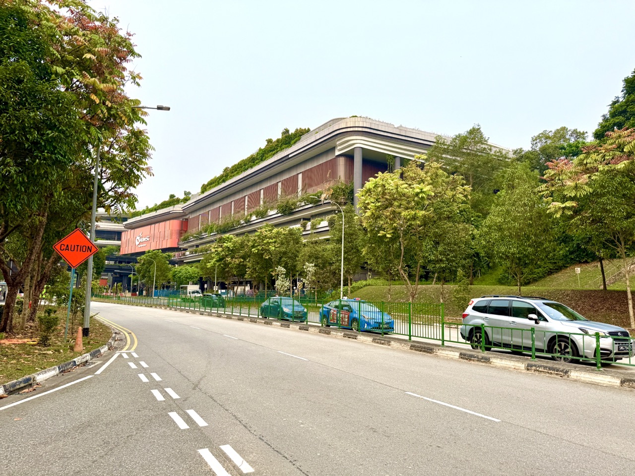
ActiveSG Punggol Sport Centre at 11 Sentul Crescent can help students understand why sports lighting, shadows and vision are important. A badminton player needs to see a fast-moving shuttlecock against its background; an outdoor visitor may notice a long afternoon shadow; and reflective water or a polished surface may produce glare. The centre began selected public operations on 27 October 2026, with its formal opening scheduled for 22 November 2026. These are contexts for learning Optics, not proof that a particular court has a specified light level, flicker rate or approved glare performance. No paid booking or visit to a restricted facility is required: accurate diagrams and gentle, safe home observations can explain the underlying physics. Live facility access belongs to MyActiveSG+.
The core idea is that light travels from a source and interacts with objects by transmission, absorption, reflection and sometimes refraction or scattering; we see an object when appropriate light from it reaches our eyes. NASA’s explanation of wave behaviour describes the main ways light interacts with matter, while The Physics Classroom explains line of sight, the law of reflection and ray diagrams. A child’s task is to distinguish an actual observation from an inference: a shiny court image does not establish measured glare, and a bright-looking sports hall does not prove identical lighting across every location. This guide moves from seeing and light sources through shadows, mirrors, images, sports visibility and safe observation, with original worked examples, practical questions and a four-week learning route.
- Setting: ActiveSG Punggol Sport Centre, 11 Sentul Crescent, near the Waterway and Sam Kee LRT.
- Physical principle: light from a source or illuminated object must reach an observer for it to be seen.
- Main behaviours: reflection, transmission, absorption, scattering and refraction.
- Ray model: arrows show idealised directions of light propagation; diagrams simplify the full wave behaviour.
- Shadows: an object can block some or all light; extended sources can create umbra and penumbra regions.
- Sports visibility: contrast, background, illumination and the observer’s position can affect how an object appears.
- Glare: excessive or poorly directed light can cause discomfort or difficulty, but actual venue measurements are not established here.
- Safety: never look directly at the Sun, shine bright beams into eyes, use lasers or change public lighting for an experiment.
- Scientific accuracy: no claim is made about Punggol’s actual lux readings, light fittings, reflectance or compliance.
- Learning progression: 4-week plan, age-appropriate diagrams, worked physics questions, FAQ and official resources.
Definition lock: what does Optics investigate?
Optics is the study of light and its behaviour, including how it travels, interacts with materials and is detected or used. In a sports setting, the learner can ask how a shuttlecock becomes visible, why a shadow appears or why a reflected image forms. Those are distinct questions even when they occur during the same game. A responsible explanation identifies the physical phenomenon before choosing vocabulary. “The court is bright” describes an impression; “light reflects from the floor into the observer’s eye” is a possible mechanism; an actual measured illuminance would require appropriate instruments and a method. Keeping these levels separate makes optical reasoning clearer.
Why a sports centre is a context, not a physics laboratory
Punggol Sport Centre is managed for sport, recreation and other authorised activities. A court booking does not permit students to darken a hall, move floodlights, project intense beams or experiment with public electrical fixtures. Such changes could disrupt play or create safety issues. The right educational approach uses a permitted exterior view, a legitimate family-owned photo or a classroom diagram. When students need a physical demonstration, choose a low-intensity safe setup suitable for the age group and supervise it appropriately. The facility is a familiar reference, not an experimental subject that visitors may manipulate.
First understand a luminous object
A luminous object emits light of its own, such as an operating lamp or the Sun. An ordinary badminton racket or wall is generally seen because light from another source is reflected toward the observer. A learner should not claim that a shuttlecock generates its own visible light merely because it appears bright in a photograph. Ask children to identify whether the object supplies the light or reflects illumination from its surroundings. This distinction begins a good line-of-sight explanation. It also teaches why an unlit court may be difficult to use even though every physical object is still present.

An illuminated object sends reflected light to us
When light reaches an object, some light may be reflected. If the reflected light travels toward an observer’s eye, the object can become visible. This principle is explained in the Physics Classroom’s line-of-sight lesson. The precise amount and direction of reflected light depend on the surface and lighting geometry. A child can draw three arrows: lamp to shuttlecock, reflected light toward eye, and the observer’s direction of sight. The diagram is a simplified model, but it makes the role of the source, object and observer easy to understand.
Why a white shuttlecock can look darker
A white shuttlecock may appear less distinct when illumination is poor, the background has similar brightness or the object is strongly backlit. Its physical material need not have changed. What the observer sees depends on light reaching the object and returning to the eye, together with surrounding contrast. Do not automatically blame a real venue’s lighting from an isolated dark photograph. Camera exposure, screen settings and the moment of capture affect how objects appear in images. Use a fictional illustration to discuss why visibility is contextual, and ask what evidence would be needed to assess real sporting conditions.
The ray model simplifies light travel
A ray is an idealised arrow showing a direction in which light travels. The ray model is useful for tracing light from a source to an object, through a boundary or toward a surface. It does not mean light consists solely of tiny rigid lines painted in space. Light also has wave behaviour and other physical descriptions that matter in different contexts. For an introductory problem, draw only enough rays to explain an observation. A student who draws thirty crossing lines without clear labels may communicate less than one who draws the correct incident and reflected paths with their directions.
Straight-line propagation in a uniform medium
In a simple geometric-optics model, light travels in straight lines through a uniform transparent medium. This helps explain a clear shadow when an opaque obstacle blocks part of a beam. However, light can change direction at boundaries, scatter in particles or show diffraction under conditions outside the simplest model. State the assumption when applying straight-line reasoning. The learner can solve a paper shadow diagram without aiming real bright light into a child’s eyes. The physical concept is spatial: what lies between source and screen determines which rays can reach each location.
Transparent, translucent and opaque
A transparent material transmits light with relatively little scattering for the intended view. A translucent material transmits light while scattering it enough to blur detailed images. An opaque material blocks transmission of visible light under relevant conditions. These are practical categories, not guarantees that every material behaves identically for every wavelength or thickness. A clear cup, frosted plastic and cardboard may help illustrate the distinction in an appropriate safe setting. Do not use specialised glass or unlabelled chemicals for a school demonstration. Ask what the observer can see through each object, and what changes when the material is placed between a light source and a picture.
Why a shadow forms
A shadow forms when an object prevents light from a source reaching a region that would otherwise be illuminated. In a basic diagram, draw a source, an opaque obstacle and a screen. The rays that just pass the obstacle’s edges define a simplified shadow boundary. A child should understand why an object cannot cast the same shadow from every light position: geometry matters. The example can use daylight and a safe everyday object, but never encourage staring at the Sun or standing in traffic to obtain dramatic shadows. A pencil diagram provides the necessary structure without environmental risk.
Umbra and penumbra are different
With an extended source, a region may receive no direct light from that source, while an adjacent region receives some but not all of it. Those regions are called the umbra and penumbra in the relevant model. NASA’s eclipse geometry explanation uses these terms to show how the relative sizes and positions of source, obstacle and screen affect shadows. A child can draw a large source and a small obstacle to predict a dark central region and a partially lit margin. The lesson is about light-path geometry, not permission to observe the Sun without protective equipment.
Why multiple light sources can make multiple shadows
If two lamps illuminate an object from different directions, each can create a different shadow contribution. Parts of a region may be illuminated by one source while blocked from another. A diagram can show overlapping shadows of different darkness. Do not assume that the photograph of a player with several faint shadows proves a particular number of installed Punggol lamps. Other reflections, camera processing and surfaces may affect appearance. The teaching value lies in explaining why the geometry of multiple sources produces more complex illumination than the single point-source model.
Shadow size depends on relative distances
A shadow can appear larger when an object is closer to a compact light source and farther from a screen, under suitable geometry. The exact relation depends on the distances and source extent. A student can use similar triangles in a hypothetical drawing to calculate a magnification factor without placing a lamp next to flammable material or using any hazardous equipment. Always label distances from the intended points. This is a link between Optics and Geometry: reasoning about rays gives an observable consequence of spatial relationships. The result is a model, not a measurement of a real Sports Centre shadow.
Worked example: simple shadow enlargement
Assume an ideal point source is 1 metre from an object, and the screen is 2 metres from the source. Under a straight-line model with the object and screen parallel and aligned, the shadow’s corresponding linear dimensions are magnified by 2 ÷ 1 = 2. An object 5cm high would create a model shadow 10cm high. These numbers are invented for teaching. The calculation does not predict every real shadow because extended sources, tilted surfaces and scattering can alter the edges. Ask the learner which assumption allowed the similar-triangle result before substituting numbers.
Reflection changes a ray’s direction
Reflection occurs when light reaches a boundary and a portion is directed back into the original medium. A mirror provides a clear school example. A court floor may reflect some light too, although its reflection may be diffuse rather than mirror-like. NASA’s light-interaction page describes reflection as one of several behaviours when light meets matter. Students should not assume all incident light is reflected. Depending on material and wavelength, light may also be absorbed, transmitted or scattered. The correct answer identifies which processes the question concerns.
The normal is a construction line
In ray diagrams, the normal is an imaginary line perpendicular to a surface at the point where a ray meets it. It is not a real beam or physical fixture. Angles of incidence and reflection are measured relative to that normal, not automatically from the surface itself. This distinction prevents a common mistake in mirror problems. A student can draw a horizontal mirror, then a vertical normal at the point of contact. If the surface is tilted, the normal must tilt with it. The angle is a relationship between lines, not a fixed orientation on the page.
The law of reflection
For ideal specular reflection, the angle of incidence equals the angle of reflection, measured from the normal. The Physics Classroom provides a guided explanation and diagrams. If an incoming ray is 35 degrees to the normal, the reflected ray is 35 degrees to the normal on the other side, under the model. The full change in direction should not be confused with either individual angle. Students can practise with a pencil and protractor rather than aiming bright beams across a room or a sporting area.
Specular and diffuse reflection
A smooth surface at the relevant scale can produce more orderly or specular reflection, while a rough surface may scatter reflected light into many directions. This helps explain why a mirror forms a distinct image and ordinary walls can be seen from many viewing positions. The distinction is not absolute for all wavelengths or all surfaces. A glossy-looking photo of a sports floor cannot establish a measured reflectance or exact microstructure. Use textbook examples and material comparisons suited to the school level. The important concept is how surface properties influence the directions of light reaching an observer.
Glare is an experience, not just brightness
Glare occurs when the distribution or intensity of light in the visual field creates discomfort or reduces the ability to see relevant details. It can depend on the direction of a source, reflection, background contrast and the observer. A person may report discomfort even when an overall photograph appears attractive. Yet an individual impression or camera image does not establish an official lighting-standard violation. If a visitor experiences difficulty seeing during a game, they should report the actual circumstances to staff rather than alter light fittings. In a lesson, discuss why placing a bright source directly behind a moving object can make visibility harder.
The importance of visual contrast
Contrast concerns differences in luminance or colour between an object and its background. A white shuttlecock may be easier to distinguish against some dark backgrounds than against similarly bright areas, although actual visibility also involves lighting, motion and the observer. Students can test this concept with printed paper shapes of contrasting colours in a safe classroom, without competitive sport or strong lighting. The purpose is not to choose an official facility wall colour. It is to see that the same object can appear more or less distinct depending on what surrounds it. A well-designed visual environment considers relationships rather than one isolated brightness number.
Refraction differs from reflection
Refraction involves a change in direction of a light ray when it crosses between media under conditions where its propagation speed changes. An example is light passing between air and water at an angle. Reflection instead sends some light back from a boundary. The Physics Classroom’s refraction lesson explains why rays bend at interfaces. A learner may use a standard diagram of a ray entering a transparent block. Do not perform optical tests by entering Punggol’s pool or placing electronic devices in water. A diagram and ordinary classroom materials are sufficient.
Why water can change an object’s apparent position
An object partly under water can appear displaced because light rays refract at the water-air boundary. The apparent image is a result of the path light takes to an observer’s eye. This makes water an interesting everyday optical context, but the demonstration must be carried out safely with suitable clean water and an appropriate object in a private setting. Do not ask a child to look into public pool water to estimate depth. Depth perception near water has safety implications, and a simple image can be misleading. Follow facility rules and supervision requirements rather than relying on an optical impression.
Scattering is not the same as refraction
Scattering occurs when light is redirected through interactions with particles or irregular structures. The sky’s appearance and the diffused appearance of a translucent surface can involve scattering. Refraction concerns a change in direction associated with passage across a boundary or through a varying refractive medium. Both can occur in real scenes, but a student should name the relevant mechanism. NASA describes scattering alongside reflection and refraction in its overview of light and matter. The learner can compare diagrams rather than require a dramatic outdoor demonstration under the Sun. Good Physics explains a mechanism before choosing an attractive example.
Absorption affects what comes back to the eye
When material absorbs some incident light energy, that portion is not available as reflected or transmitted visible light at the same wavelength and direction. Objects often appear coloured because their reflected and transmitted spectral content differs from the illumination. A black sports bag and a white bag may behave differently under daylight, but it is too simple to claim every black object always absorbs all light. Surface composition and wavelength matter. A child can compare printed colours under ordinary safe lighting and discuss the limitations. Do not use concentrated sunlight or magnifiers to heat materials during the activity.
Why shadows change across the day
The apparent position of the Sun changes across the sky as Earth rotates. As its direction changes relative to an object, the direction and length of a shadow on a level surface can change. Local weather, obstacles and surface geometry also matter. A family can study a series of legitimate dated photographs or diagrams without standing outdoors for long periods during high heat. Do not claim a particular Punggol walkway is always shaded based on one picture. A shadow at 9am may be different at 3pm. The scientific explanation depends on source direction, not on a building moving during the day.
The difference between illumination and camera exposure
A bright-looking photograph can result from camera settings such as exposure time, sensor sensitivity and image processing, not just a brighter real environment. Conversely, a dark image does not prove a sports hall is insufficiently lit. A learner can compare two pictures of a still object taken with different settings in an appropriate private location and observe how the displayed image changes. The exercise does not require professional photography or facility access. The important lesson is that an image is a processed record, not a direct numerical light measurement. This connects Optics with the critical interpretation of visual media.
Illuminance has a unit
Illuminance describes luminous flux arriving at a surface per unit area, and the SI-derived unit is the lux, equivalent to one lumen per square metre. This does not mean a photograph’s pixel brightness is a lux value. Actual illuminance measurement requires appropriate calibrated instruments, positions and methodology. Students can learn the definition without estimating public sports-hall values. If a school problem provides fictional lux readings, analyse them as numerical data under the stated conditions. Do not invent an exact Punggol measurement or assert compliance with a sport-standard threshold without verified technical documents.
Luminance and illuminance are different
Illuminance concerns light arriving at a surface, while luminance relates to light emitted, reflected or transmitted in a particular direction per projected area. Perceived brightness is more complicated still because the visual system responds to the scene and context. These distinctions are more advanced than an early Primary pupil needs, but they help older students understand why “lots of light on the floor” is not the same as “easy to see a shuttle against a bright wall.” The correct visual design considers more than one quantity. A blog cannot determine the actual Punggol lighting quality from a façade photo.
Inverse-square reasoning needs assumptions
For an ideal point source radiating uniformly into open space, illuminance on a suitably oriented surface can decrease with the square of distance under the model. Double the distance and the value can become one quarter, subject to assumptions. A sports hall with many extended luminaires and reflecting surfaces does not behave as a single isolated point source. The formula remains useful for illustrating the role of distance, but students must not apply it blindly to certify real lighting. A good answer states source geometry, orientation and environmental assumptions before calculating. The model explains why proximity can matter without replacing professional design.
Worked example: an idealised source

Suppose a hypothetical ideal point source produces 400 lux at a particular directly facing reference location in an otherwise simple model. At twice the distance, under the inverse-square assumptions and same orientation, the model predicts 400 ÷ 4 = 100 lux. This is an invented numerical illustration, not a reading at any Punggol facility. A student should ask what changes if a second lamp is introduced or a reflecting wall is present. The calculation is valuable precisely because its limitations can be discussed. Real spaces require more than one distance and a tidy formula to describe illumination.
Why flicker cannot be diagnosed from one photo
Some artificial lighting can vary in light output over time. Camera shutter effects and rolling-sensor behaviour may produce bands or artifacts that are not experienced the same way by human observers. A single photograph cannot establish an exact light-source flicker frequency or clinical impact. Avoid making a health diagnosis or public allegation from social-media imagery. If a visitor notices a persistent concerning lighting condition, they should report the experience to the operator. Students can learn the concept from credible educational diagrams and distinguish recording effects from the actual source. No one should modify public lighting or provoke visual symptoms for a lesson.
Shadows and sport timing
A ball or shuttle travels through positions that may differ in background and illumination. A shadow on a court surface may help an observer perceive position in some circumstances, but it can also shift with the lighting. The relationship is complex and sport-specific. Students should avoid claiming that players always rely on shadows in one fixed way. A useful home exercise might use an illustrated sequence of an object and its shadow under a single known light source, then ask how the shadow position changes when the source moves. This keeps the Physics question clear without teaching unverified professional tactics.
Sports lighting is a professional design responsibility
Suitable lighting for sport may involve illuminance, uniformity, glare control, colour appearance, flicker characteristics and requirements of the specific activity or competition. The relevant standards and measurements need careful definition. This article does not certify Punggol Sport Centre against any particular lighting standard or propose alterations to installed fixtures. A student can learn why professionals would need multiple measurement points and observer positions. That is an engineering question, not a reason to climb lighting masts, enter plant rooms or move equipment. Understanding the design factors is meaningful without claiming to have evaluated a real facility.
A roof or shade structure has several purposes
Shade can alter direct sunlight reaching a person or playing area. A roof also protects from some weather conditions, but it does not automatically control every temperature, reflection or visual issue. A covered outdoor court may still receive side light, and an enclosed hall may have artificial lighting with different characteristics. A child can draw three cases—open sun, roof shade and indoor illumination—then identify the possible light paths. Avoid using the drawing as proof that a particular Punggol court is safe during lightning or severe weather. Current operator decisions and official advisories remain necessary for real activity.
Mirrors are useful models, not public sport props
A plane mirror can demonstrate the law of reflection and image formation in an appropriate classroom. A student may draw an incident ray, the surface normal and a reflected ray to predict what an observer sees. However, bringing a large mirror into a booked sports hall would create hazards and interfere with other users. Use a small safe classroom mirror where suitable, under supervision, or a paper ray diagram. Do not aim reflected sunlight into eyes or toward traffic. The goal is understanding the direction of light, not obtaining the brightest possible reflection.
Image formation in a plane mirror
A plane mirror produces an apparent image behind the reflecting surface for an observer, with familiar geometric properties in the ideal model. Students can study rays that reflect toward the eye and extend them backward in a diagram to locate the virtual image. The apparent image is not a real object placed behind the mirror. This helps explain why a mirror can seem to contain a second room even though it reflects light from the real environment. School exercises should keep the model clear and not confuse reflected images with actual venue routes or people. The Physics Classroom provides appropriate introductory mirror diagrams.
A camera and the eye have different roles
A camera forms and records an image through an optical system and sensor, while the human visual system processes light through the eye and brain. Their responses to brightness, colour and motion are not identical. A smartphone screenshot of a court can therefore look different from the live view. Students should not diagnose a person’s eyesight from camera settings or compare visual acuity using an improvised court test. The useful concept is that detecting and representing light depends on the observing system. An advanced learner can explore focus and image formation from diagrams without collecting private biometric information.
Vision differences require respectful communication
People may have different visual abilities, sensitivities or needs. A participant who struggles to see the shuttle should not automatically be told that they are careless or unfit. Appropriate professional eye care may be relevant where symptoms persist, while environmental conditions and instructions can also matter. An independent article cannot diagnose the cause. A group organiser can ask how to support participation within venue and safety rules without demanding medical details publicly. Optics education becomes more humane when it distinguishes the physics of light from assumptions about someone’s health or personal effort.
Never look into the Sun for a school task
Direct observation of the Sun can cause serious eye damage. A shadow exercise does not require staring at the light source, using a magnifying glass or pointing a telescope or camera without correct protection. Use an ordinary safe paper model, or observe the shadow on the ground without looking toward the Sun. Do not attempt eclipse viewing without appropriate certified equipment and expert guidance. Families can learn umbra and penumbra from NASA diagrams entirely indoors. The success of the lesson depends on understanding light paths, not experiencing a dazzling beam or bright astronomical event first-hand.
Lasers are not needed for the lesson
Laser pointers can create avoidable eye hazards when misused, especially around children, reflective surfaces and public spaces. There is no need to bring one to a sports centre to draw rays across a court. A pencil line with an arrow represents the direction of travel without physical danger. If a supervised school lab uses optical equipment, follow the teacher’s designated procedures and protective requirements. Do not substitute an inexpensive unverified laser into a home experiment. Visual impact is not a good reason to create risk when the same concept can be taught with clear diagrams.
Do not use a live sports court as a shadow screen
A child might imagine placing objects on a court to study shadows, but real players need unobstructed surfaces. Objects left on the floor can create trip or slip hazards, and interfering with another booking is inappropriate. A piece of white paper or a home table is enough for safe modelling. No venue reservation, filming permission or special lighting access should be assumed. A good Science lesson respects the purpose of the public space while moving experimental activity to a suitable setting. This boundary also teaches that scientific curiosity and everyday responsibility should reinforce each other.
Original case study: the white shuttle on a bright background
A fictional beginner says they sometimes lose sight of a white shuttle when it crosses a very bright background. The parent explains that object-background contrast and lighting geometry can affect visibility. They do not claim the new Punggol hall has failed an official standard or that the child’s eyesight is faulty. Instead, they use simple drawings showing a pale object against light and dark backgrounds. The child compares which drawn example is easier to distinguish under comfortable viewing. This is a qualitative illustration, not a calibrated test of vision or professional sports lighting. The correct conclusion remains limited to the examples used.
Original case study: a long afternoon shadow
A family sees a long shadow in a dated Waterway photograph taken late in the day. A child asks why it seems different from a noon photograph. The parent introduces the Sun’s changing apparent direction and ray geometry, while reminding the child that weather and camera angle also differ. They draw one source-object-ground diagram for each situation. No outdoor exposure at risky times is necessary. The child learns that a photograph of a shadow provides evidence about a captured moment but not a complete schedule of shade for every day. The lesson links observation, time and model assumptions.
Original case study: an apparently bent racket
A child places a suitable straight plastic ruler partly into a safe clear container of water under supervision and notices it appears displaced at the water surface. The adult explains refraction and draws rays passing between water and air. They do not repeat this with an electrical device or attempt it at the public swimming complex. The effect is an optical change in apparent position, not evidence the ruler has physically bent. The simple home demonstration connects an unusual observation to a known boundary behaviour while making the limits of the model explicit. The container should be stable and used in an appropriate safe environment.
Original case study: two lamp shadows
In a hypothetical diagram, two lamps illuminate a cardboard object from different directions. The child predicts where a region might be lit by one source but shadowed from the other. The family can colour the resulting zones on paper without turning on bright lights. They discover that multiple sources create overlapping illumination patterns rather than one perfect single-source shadow. The explanation assumes simple point-like sources, so real shadows can be softer or more complex. The educational outcome is an understanding of how geometry affects light distribution. A clear drawing is sufficient evidence that the child can reason about the setup.
Original case study: an image too dark to interpret
A student sees an online image of Punggol Sport Centre that makes the court appear dim and concludes the lighting is defective. A parent explains that the image may have been underexposed or displayed on a dark screen, and the exact facility, time and conditions are not confirmed. The child revises the claim: “The picture looks dark, but no actual lighting measurement is provided.” That is a stronger scientific statement. The family can then read about illuminance and glare from appropriate sources. Critical interpretation avoids both dismissing someone’s real difficulty and making a public accusation from insufficient evidence.
A paper ray-diagram practice
Draw a source at the left, an opaque obstacle at the centre and a viewing surface at the right. Use a ruler to draw two rays just passing the obstacle’s edges, then shade the idealised unlit region. Add a second light source in a different colour and identify where the two shadows overlap. Students should describe the assumptions: straight rays and sources treated as small points unless otherwise specified. This is a safe reusable lesson for Primary or Secondary levels. The paper diagram can be more informative than a complicated photograph because each geometric relationship is deliberately visible.
A reflection-angle practice
Draw a horizontal mirror segment and a vertical normal at its midpoint. Create an incident ray that makes 40 degrees with the normal and ask for the angle the reflected ray makes with the normal. Under the ideal specular law, the answer is 40 degrees. Then rotate the mirror diagram and ask whether the equality changes. It does not. The learner should explain what the angle is measured from, not merely quote the number. This short exercise teaches the relationship before moving to more elaborate mirror-image problems. No bright physical light source is required.
A colour-and-absorption question
A child asks why a dark sports bag appears different under white light and coloured light. The parent explains that the light reaching the object and its wavelength-dependent reflection can alter appearance. A bag that looks blue under ordinary illumination may look different if the illuminating spectrum lacks certain wavelengths. This is a conceptual example, not an instruction to use bright coloured LEDs or lasers. Use suitable teacher-approved illustrations where necessary. The child should avoid claiming that every colour is produced by one perfect reflected wavelength. Real materials and human colour perception can be more complex than an introductory diagram.
How to choose an age-appropriate optics question
A younger Primary child may begin with light and shadow, identifying sources and illuminated objects. Older Primary pupils can use straight-ray models and simple reflection where appropriate to their curriculum. Secondary learners can develop incidence angles, refraction, images, frequency and quantitative models under their actual syllabus. Do not force lens formulas on a child who has not yet understood why an object casts a shadow. Start from a familiar observation and add one principle at a time. The goal is conceptual understanding, not covering every optical term in one sitting. A good teacher diagnoses the missing link before adding a harder calculation.
Four-week optics learning plan
Week one: identify light sources, illuminated objects and the path from object to eye. Week two: explore shadow geometry, point and extended sources, umbra and penumbra on paper. Week three: learn reflection, the surface normal, and refraction through diagrams and safe simple examples. Week four: discuss contrast, glare, illuminance, image exposure and why real sport lighting requires professional evidence. Every stage can happen at home or in a supervised classroom. The family need not enter any closed ActiveSG area or handle high-intensity lighting. Success means explaining which light behaviour produces which observation and stating the model’s limits.
Common optics misconceptions
A white object does not always look equally bright; contrast and illumination matter. A shadow does not prove light is absent from the entire scene. A ray diagram is not a physical cord of light. A photograph cannot establish lux levels or verify compliance. A shiny surface is not a perfect mirror at every scale. Glare is not identical to total illuminance. Refraction and reflection are not the same change. A curved roof or bright room image does not tell us the installed lighting design. The correct approach is to identify the light path, surface interaction, observer and evidence, then refrain from unsupported technical claims.
Frequently asked questions
Can children learn light and shadows without a court booking? Yes. Safe paper ray diagrams and ordinary supervised home examples are sufficient.

What lets us see a shuttlecock? Appropriate light from the illuminated object must reach the observer’s eyes.
Is light reflection the same as refraction? No. Reflection redirects light back at a boundary, while refraction involves a directional change during transmission across media under suitable conditions.
What is an umbra? In the usual shadow model, it is a region receiving no direct light from the relevant source.
What is a penumbra? A region where an extended source is only partly blocked.
Does a dark photograph prove poor venue lighting? No. Exposure, screen settings and context may affect appearance; actual assessment requires appropriate evidence.
What is the law of reflection? The angle of incidence equals the angle of reflection, both measured from the normal, for ideal specular reflection.
Is a lux reading visible in a photograph? No. Lux is a measured illuminance unit; a photo is not automatically a calibrated measurement.
Can children use laser pointers at the sport centre for school Physics? Do not do so. Use safe classroom demonstrations or diagrams and follow venue restrictions.
Have Punggol’s actual sports-hall lighting levels been certified here? No. This educational guide makes no project-specific photometric or safety certification.
Official sources and next step
Begin with NASA’s behaviours of light, NASA’s explanation of umbra and penumbra, The Physics Classroom’s reflection lessons and its refraction overview. SportSG’s official Punggol opening listing confirms the planned 22 November 2026 event, while MyActiveSG+ provides live access details. Companion eduKate guides explain sports acoustics, geometry of courts and observational visual art.
Your next step: draw a safe ray diagram with a light source, an object, a surface and an observer. Explain one reflected path and one shadow region, then name what extra evidence would be needed before judging actual sports-hall lighting.
Editorial note: Independent optics education guide prepared 5 November 2026. No on-site Punggol photometric testing or diagnosis was conducted, and no right to modify or photograph public sports lighting is implied.


